Introduction to cross flow fan
Time:2018-6-16 Click:
The cross flow fan was first proposed by French engineer Mortier in 1892. The impeller is multi blade, long cylindrical and has forward multi wing blades.
| Chinese name | Proposed time | Proposed character | Proposed location |
| Cross flow fan | 1892 Year | Mort | France |
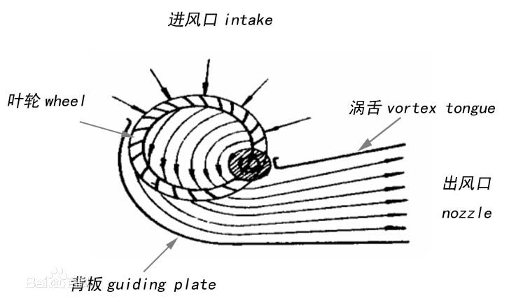
working principleCross flow fan, also known as cross flow fan, was first proposed by French engineer Mortier in 1892. The impeller is multi blade, long cylindrical and has forward multi wing blades. Its structure is shown in the right figure. When the impeller rotates, the air flow enters the cascade from the open part of the impeller, passes through the interior of the impeller, and is discharged into the volute from the cascade on the other side to form the working air flow.
Flow of air flow in impeller
It is very complex. The air velocity field is unstable. There is also a vortex in the impeller, and the center is near the cochlear tongue. The existence of vortex makes the output end of the impeller produce circulating flow. Outside the vortex, the air flow streamline in the impeller is in a circular arc shape. Therefore, the velocity at each point on the outer circumference of the impeller is inconsistent. The closer it is to the vortex center, the greater the velocity, and the closer it is to the vortex shell, the smaller the velocity. The air velocity and pressure at the fan outlet are not uniform, so the flow coefficient and pressure coefficient of the fan are average. The position of the vortex has a great influence on the performance of the cross flow fan. The vortex center is close to the inner circumference of the impeller and close to the worm tongue, and the fan performance is good; If the vortex center is far from the vortex tongue, the area of circulating flow increases, the fan efficiency decreases and the flow instability increases.
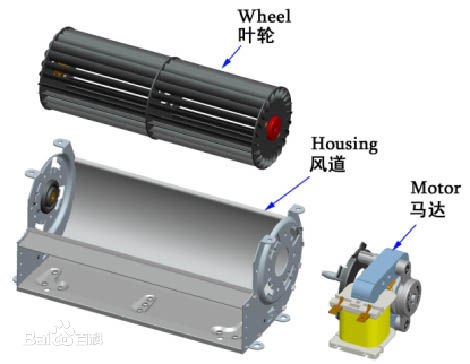
Fan structureThe cross flow fan is mainly composed of impeller, air duct and motor.
The impeller material is generally aluminum alloy or engineering plastic. Aluminum alloy impeller has high strength, light weight and high temperature resistance, and can maintain long-term and stable operation without deformation; The plastic impeller is made by injection molding and ultrasonic welding. It is generally used in low speed occasions with large diameter.
The air duct is generally formed by stamping metal sheet, and can also be cast by plastic or aluminum alloy. The casing adopts streamlined design, which can effectively reduce the loss of air flow and greatly improve the working efficiency of the fan.
The motor is the power part of the cross flow fan, which can supply AC power or DC power. AC power supply mainly includes shaded pole motor and capacitor starting motor, and DC power supply is DC brushless motor. Generally, the drive motor and impeller are flexibly installed and fixed on the air duct.
Advantages and disadvantages1) The axial length is not limited, and the length of the impeller can be arbitrarily selected according to different use needs;
2) The airflow flows through the impeller and is affected by the secondary force of the blade, so the airflow can reach a long distance;
3) No turbulence and uniform air outlet;
4) Because the air flow is forced to turn in the impeller, the pressure head loss is large and the efficiency is low;
Fan applicationCooling and heat dissipation: electronic machines, dry-type transformers, photocopiers, projectors, computers, etc;
Ventilation: rooms, public places and vehicles;
Industrial machinery: constant temperature and drying machinery; Cold and warm room equipment;
Household appliances: Freezer and display cabinet, air conditioning fan (air conditioning fan, building fan, tower fan), air heater, electric fireplace, air curtain machine, embedded oven, etc.
Flow and wind pressureTwo important parameters for the aerodynamic performance of cross flow fan are: flow and wind pressure
flowAlso known as air volume, it is usually measured by the volume of gas flowing through the fan per unit time. Its value shall be obtained through aerodynamic performance test. The common units of engineering include cubic meter / minute (CMM) and cubic foot / minute (CFM), 1cmm = 35.35cfm.
| Abbreviation | Full name | Unit symbol |
| CFS | Cubic feet per second | ft3/s |
| CFM | Cubic feet per minute | ft3/min |
| CMS | Cubic meter per second | m3/s |
| CMM | Cubic meter per minute | m3/min |
| CMH | Cubic meter per hour | m3/h |
| L/s | Liter per second | L/s |
| L/min | Liter per minute | L/min |
pressureAlso known as wind pressure, it refers to the pressure rise of gas in the fan, or the difference of gas pressure at the inlet and outlet of the fan. Its common unit is Pascal (PA), which can be divided into static pressure, dynamic pressure and total pressure:
? static pressure PS: the pressure of the fan to overcome the ventilation resistance, which is the pressure of the gas acting on the surface of the object parallel to the air flow. It is measured through a hole perpendicular to its surface.
? dynamic pressure PD: dynamic pressure refers to the kinetic energy per unit volume of fluid.
? total pressure: it is the algebraic sum of dynamic pressure and static pressure
Generally, the fan only adopts the fan static pressure characteristic curve (ps-q), as shown in the right figure. It is a series of wind pressure PS and air volume Q measured by changing the fan air resistance for many times. As shown in the right figure, the solid line FPC is the fan characteristic curve, which needs to be measured by wind tunnel test; The dotted line SRC is the system wind resistance, which also needs to be measured by the wind tunnel. The junction point of FPC and Src is the operating condition point OP, and QB and Pb are the corresponding air volume and air pressure.
national standardGB / T 3235-1999 basic types, dimensional parameters and performance curves of fans
GB 10080-2001 safety requirements for ventilators for air conditioning
GB / T 1236-2000 performance test of standardized air duct for industrial fan
GB / T 2658-1995 general specification for small AC fans
GB / T 13933-2008 small cross flow fan
JB / T 6444-1992 general technical conditions for fan packaging
Introduction to Baidu Encyclopedia of cross flow fan